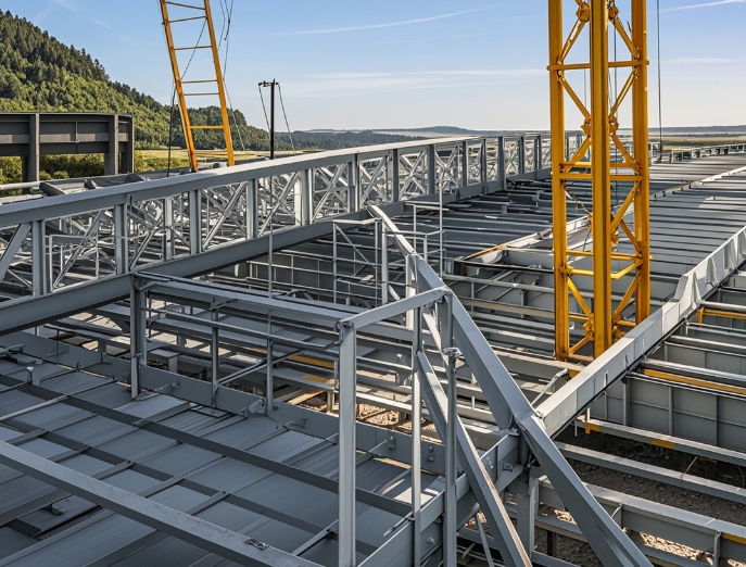
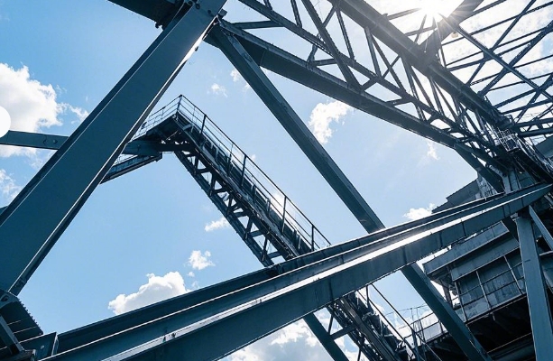
Grid welded steel plate node
更新时间:2021-02-04 09:40:30•点击:70015 • Grid Knowledge
The connection welds between the rods and the cross gusset plate and the cover plate are generally fillet welds. In the welded steel plate joints without cover plates, two sides are generally used. Three-sided welding or L-shaped welding (connection The strength can be carried out according to the shear of the fillet weld). When the fillet weld can only be set at the tip of the angle steel limb, and the back of the limb cannot be welded, the connection method of the Ayong groove welding and the fillet weld can be combined, that is, on the basis of the fillet weld at the tip of the angle steel. An elliptical slot is opened on the angle steel at the joint with the single steel plate, and fillet welds are applied along the periphery of the slot to improve the bearing capacity of the connection. Its basic failure feature is effective shearing along the weld and its load-bearing capacity can be calculated as general fillet welds.
For the cross gusset plate subjected to bidirectional force, only the influence of the force in its own plane needs to be considered in the design, and the influence of the force in the other direction can be ignored.
When there is no cover plate, the cross plate node can be designed according to the assumption of flat section. When there is a cover plate, the joint work of the cross gusset plate and the cover plate should be considered. The magnitude of the force between them is related to the ratio of their tensile and compressive stiffness.
In welding steel plate joints, the middle vertical weld of the cross gusset plate is the key weld of the joint. It has to withstand the stress from the gusset plate in two directions, and the stress situation is more complicated. The test and analysis results show that for the middle vertical weld of groove welding, when the gusset plates in both directions are under tension or compression, the normal stress of the normal section is basically the same as the external force applied by the normal stress direction lock. The ratio changes, while the shear stress of the normal section is smaller, which conforms to the theoretical stress state of bidirectional stress. However, when the gusset plates in the two directions are always tensioned and always compressed, that is, when the signs of the stresses transmitted by the gusset plates are different, no matter whether their absolute values are equal or not, larger shear stresses will be generated in the weld. When the values of tension and pressure applied in both directions are equal, the maximum shear stress value is almost equal to the stress value transmitted from the gusset plate. Since the shear strength of butt welds is lower than the tensile and compressive strengths, the shear stress will become the controlling factor when designing the middle vertical welds of the cross gusset that is always tensioned and compressed.
When designing the middle vertical weld of the cross gusset plate for groove welding, it should be treated differently according to whether the signs of the stress transmitted from the gusset plate in two directions are the same. When the stresses in the two directions are the same, the welding seam strength can be checked approximately according to the maximum stress transmitted from the gusset plate, and the design value of the welding seam and compressive strength can be used in the checking calculation. When the signs of the stress transmitted from the gusset plate in the two directions are different, in addition to checking the tensile and compressive strength according to the above method, the shear strength should be checked. The shear stress value can be approximated by the gusset plate in the two directions. The absolute value of the maximum stress is multiplied by the coefficient p.
The thickness of the gusset plate can generally be selected with reference to the selection method of the thickness of the plane truss gusset plate, and the value can be obtained according to the maximum internal force of the grid with reference to Table 3-12. For intermediate nodes, the smaller thickness in the table can be selected; for support nodes, the larger thickness in the table can be selected. Then it is decided based on the comprehensive consideration of the grid span, working conditions and node structure. If the gusset plate is too thin, it is easy to cause welding bite and large welding deformation, and it is also easy to cause lateral buckling of the joint.
Recommended Reading
-
Full analysis of seismic design and maintenance of grid structure
2025-02-27 16:16:52•1259411 次
-
What are the key process points to follow in order to ensure the quality of grid processing?
2025-02-27 11:21:00•151819 次
-
What type of construction is the grid mainly suitable for?
2025-02-25 16:42:00•148443 次
-
Quality control requirements of grid manufacturers!
2025-02-25 16:02:44•283668 次
